Arm manufacturing steps
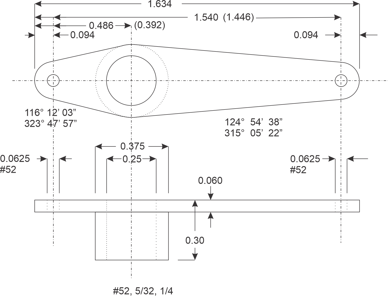
On the servo arm there are 4 critical dimensions: The distance between the three hole in the arm, the height of the arm (0.3") and the thickness of the arms (0.060"). The thickness of the walls of the column is also important (0.0625").
To avoid boredom, I am making the servo arms (and brackets) in batches to match the clusters of two or three poles as I installed them, instead of all 56 at once.
First step chop off 1 11/16" plus pieces of 3/8" square aluminum bar. Need 1.634" plus some to clean off saw marks and square the ends.
2. Using a parallel in the vise, mill two opposite sides of the stock to the required 0.30" thickness in one dimension and square one end. The other dimension can remain the extruded 3/8". All the material on the 3/8" sides will be removed except for a line along the column. All measurements are made from the one squared end, the other end will be mill later.
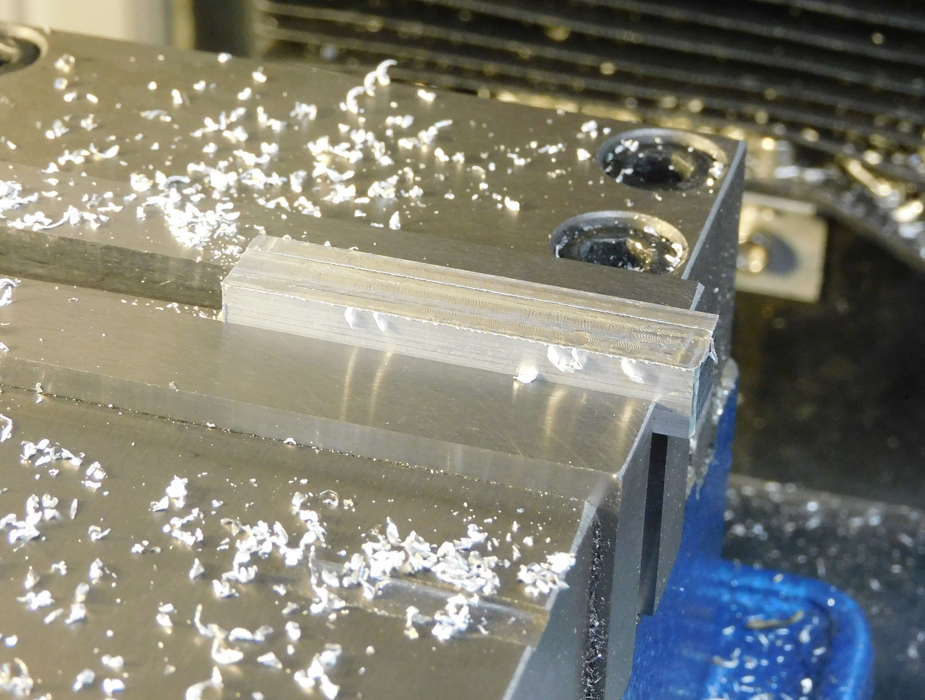
In the vise with jig A:
3. Center drill the three holes. I used a dial height gauge to mark the location of the first hole. With the jig and X-axis DRO all other holes in a batch are located.
4. Drill the three holes with a #52 bit.
5. Drill center hole with 5/32" then 1/4" bits.
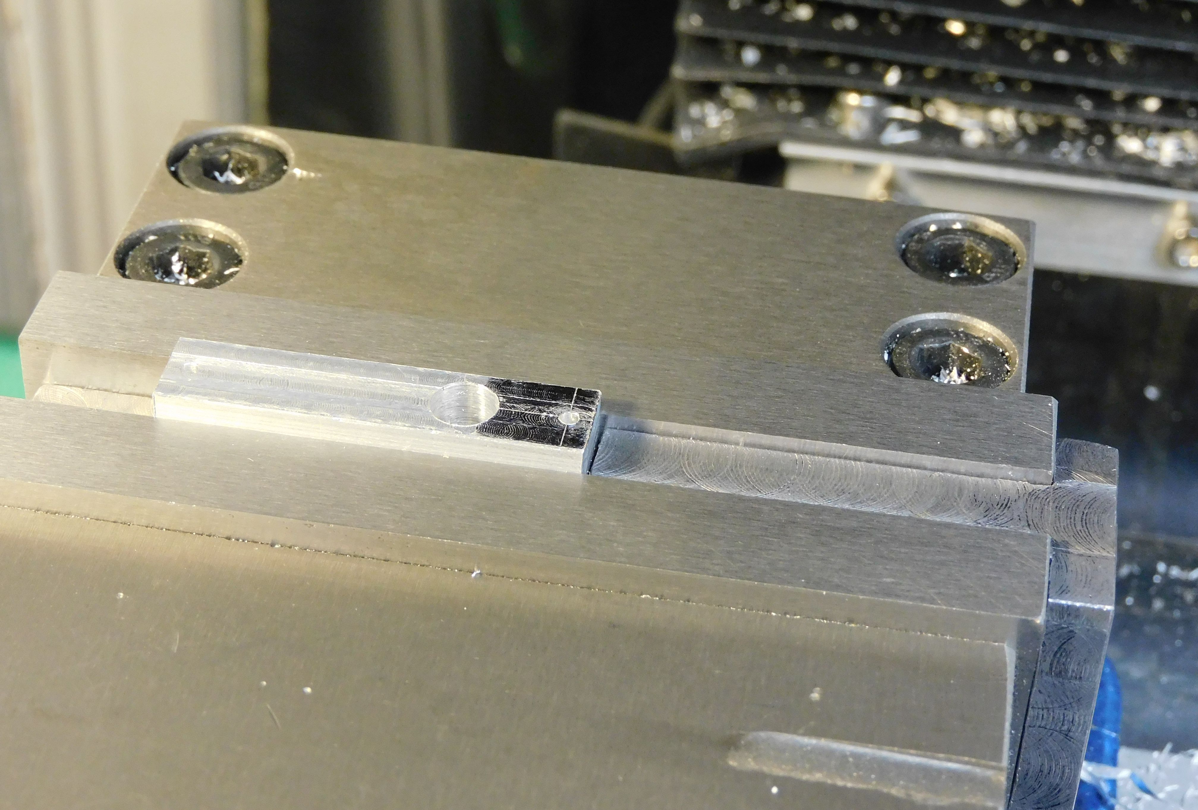
On the rotary table with jig B use the small pin to center each part.
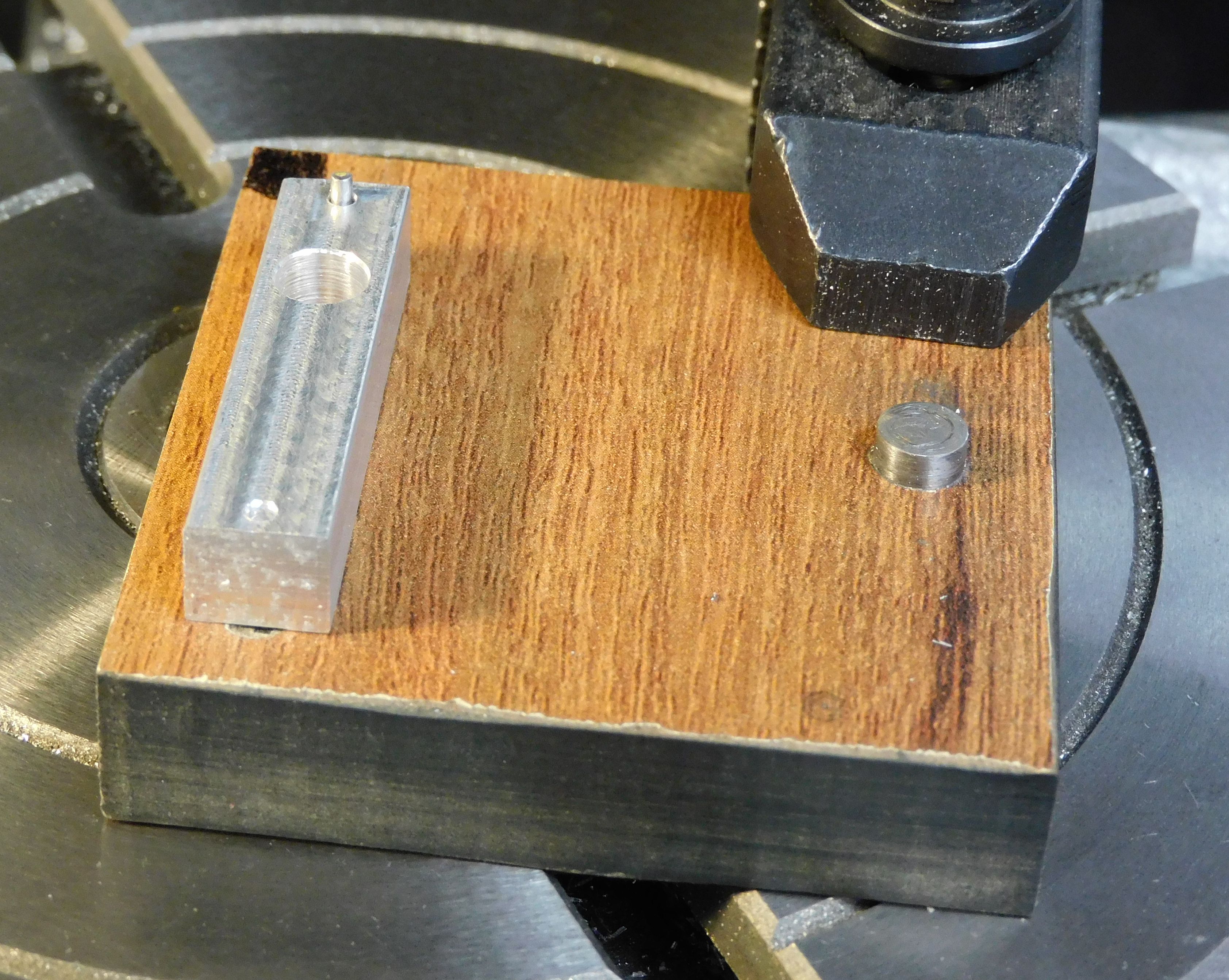
6. Shape short end. Touch off the Y-axis on the end by the black dot. Rotate the part and table until the needed sloped is parallel to the X-axis then cut using the X-axis. Shape both sides of the short end. See NOTE at the end for how to calculate the angle needed to rotate the part to shape the arm.
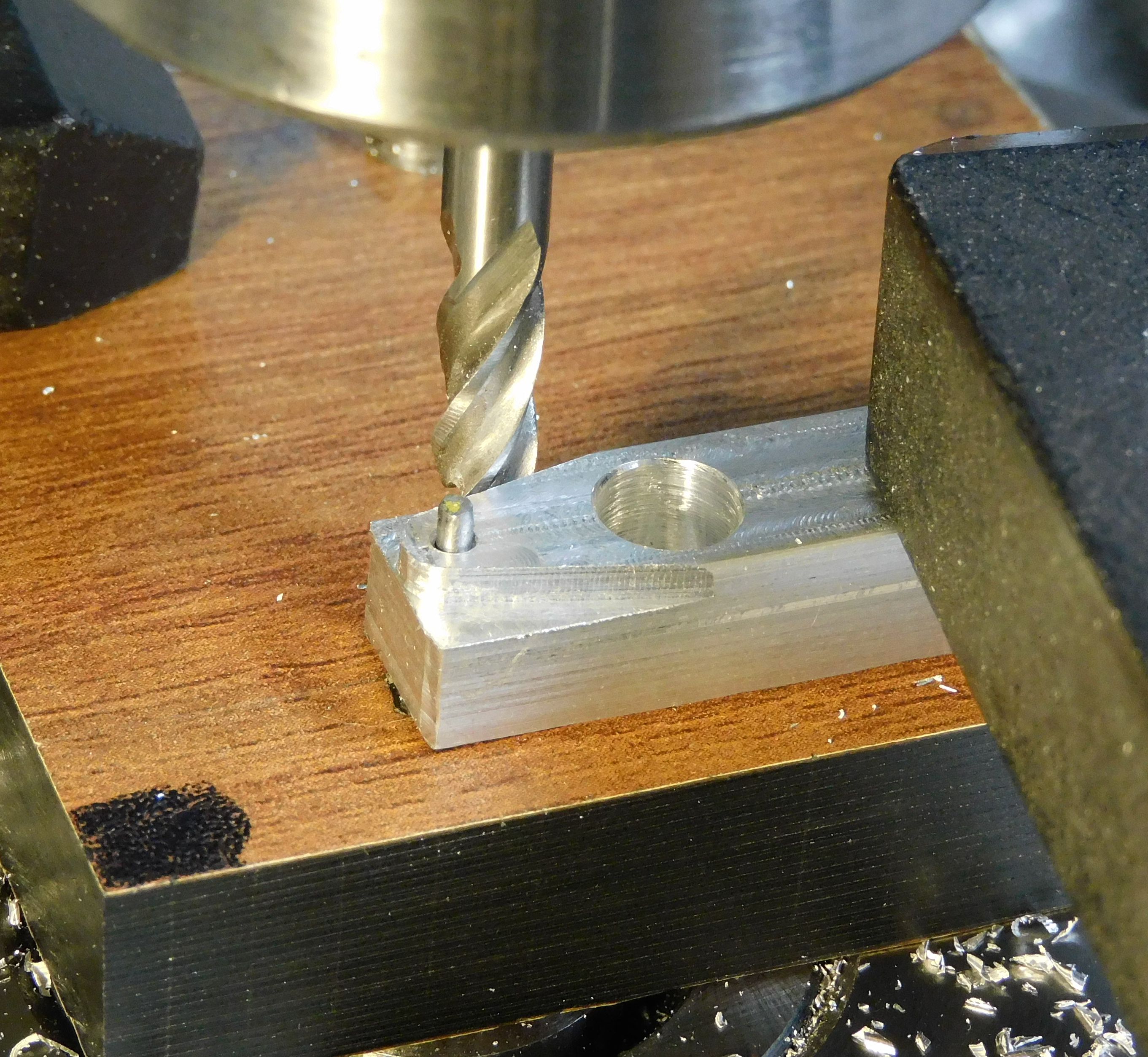
7. Reposition the part and similarly shape long end.
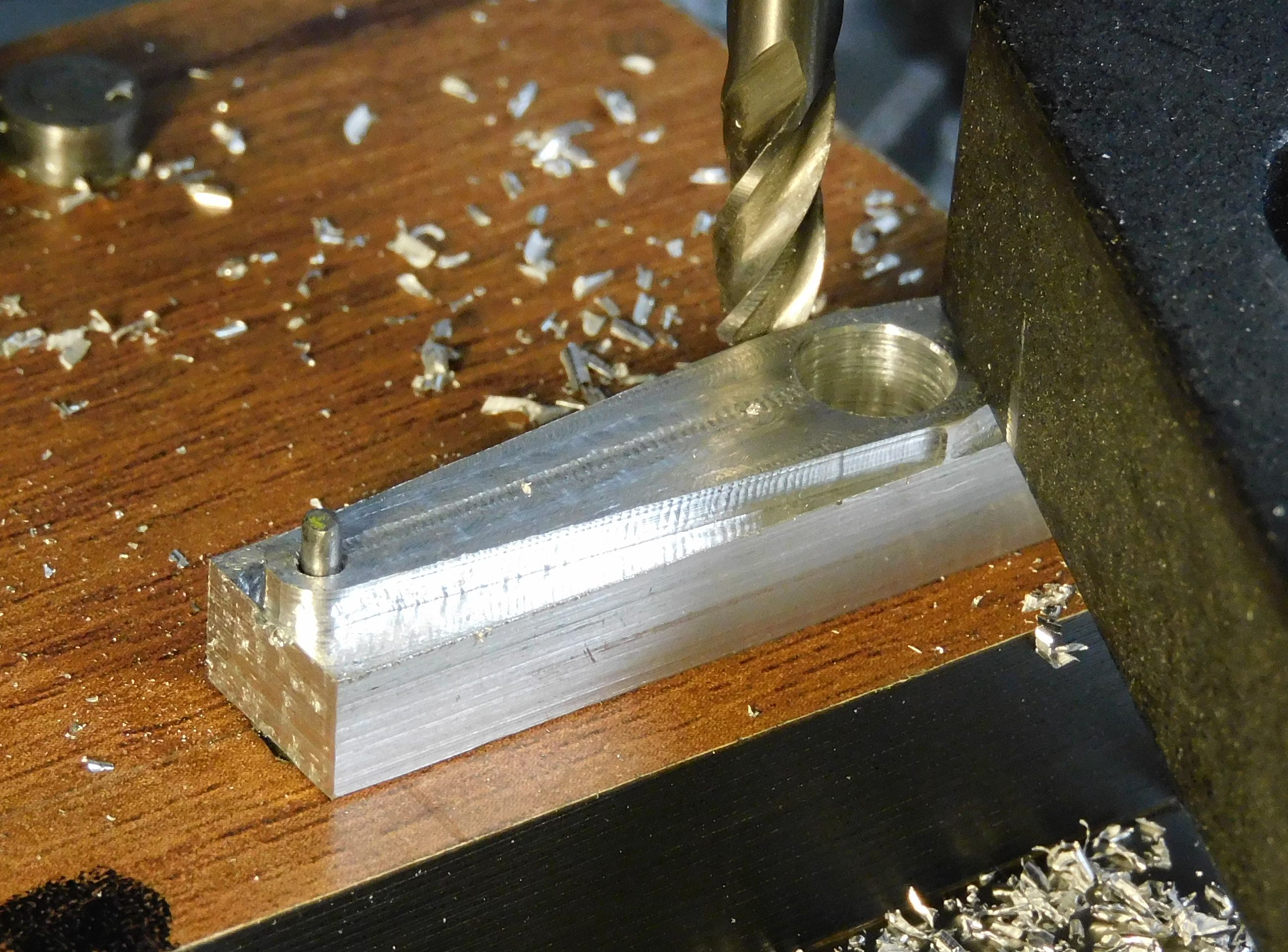
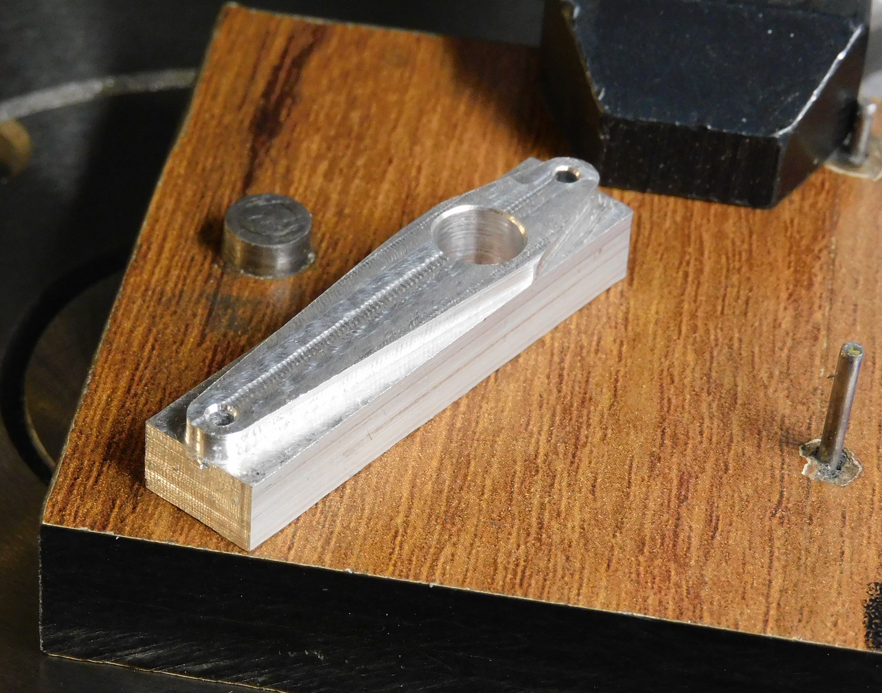
On the rotary table with jig B use the 1/4" pin to center the part in the table, shaped-side down. I used a small tool and took small bites of the waste to keep the tool pressure low. The long end is ~1"long and only 0.06" thick.
8. Cut most of the long end to thickness starting at the end.
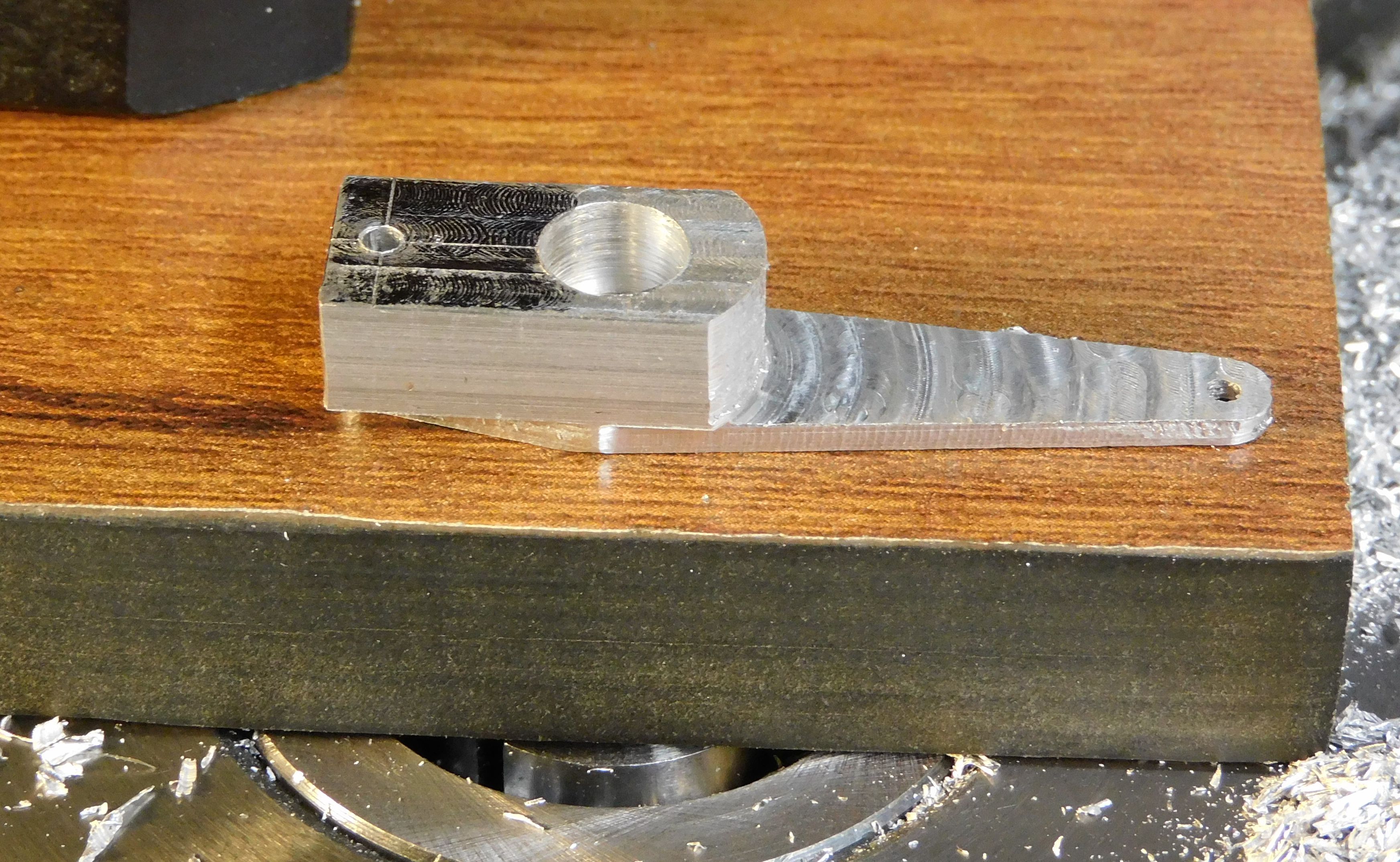
9. Cut most of the short end to thickness.
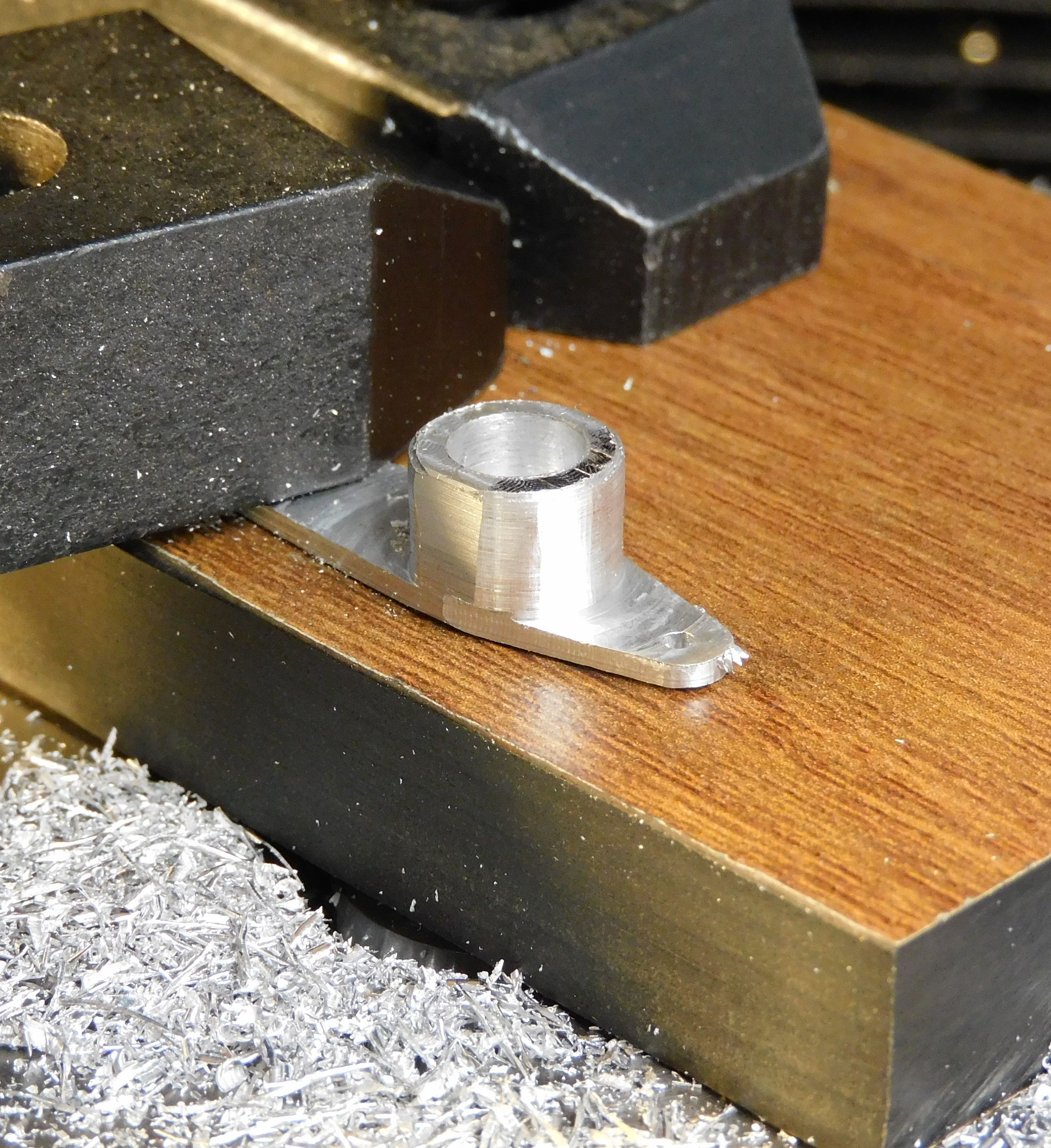
10. Cut the center column to 3/8" diameter and finish milling arms to thickness.
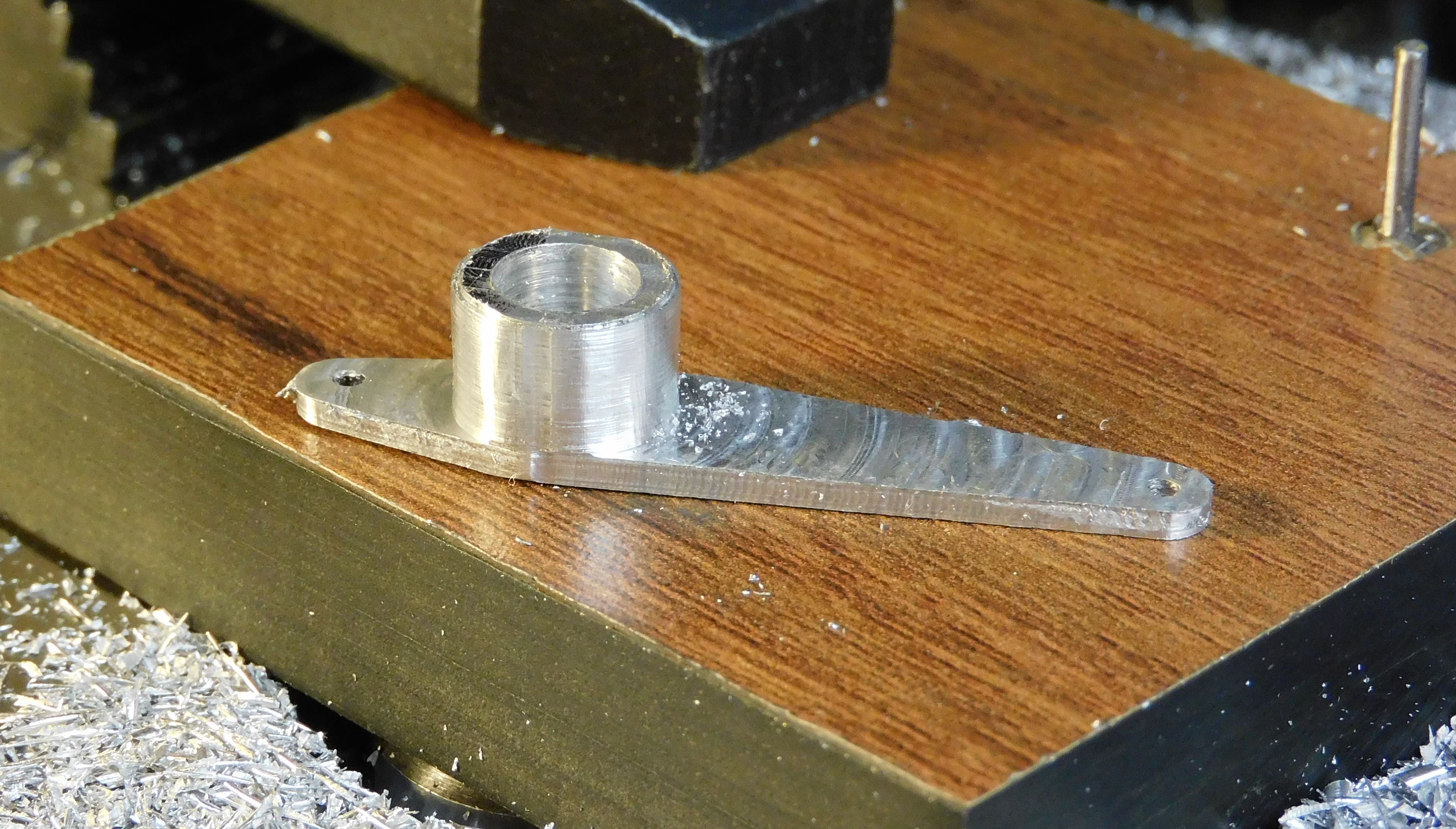
I left out several de-burring steps and axial centering tool setup steps.
NOTE: To shape the arm takes a little geometry and a little trigonometry.

The question is 'How can the part be positioned on the mill to cut each of the four diagonal edges?' At left is part of the servo arm drawing, rotated 90° to match how the part is mounted on the mill and rotary table, with the centerline on the Y-axis and the X-axis running left-to-right and the center of table rotation through point e, the small hole in the end of the arm.
One of the edges we want to cut, line bd, is tangent to the circles centered at e and at c. By definition, the tangent is perpendicular to the radius ed (and cb). If we rotate the figure around point e, as show be the red arrow, until line ed is vertical, the tangent, line bd, will be horizontal, matching the X-axis. The part can then be moved along the X-axis to cut the diagonal edge. So the question becomes what is the angle shown by the red arrow, or angle aed?
Triangle aed is a right triangle with a right angle at d (radii ed perpendicular to the tangent). Triangle acb is a similar right triangle with angle acb = angle aed.
Now construct line ef, perpendicular to cb going through point e. This makes rectangle, efbd, so line fb = ed.
With trigonometry we can now find angle ecf which is equal to aed, the angle we want to know.
From the drawing, the radius of the circle at e, ed = 0.094 = fb.
From the drawing, the diameter of the circle at c = 0.375 so
The radius of the circle at c, cb/2 = 0.375/2 = 0.1875
From the drawing, the hypotenuse of triangle ecf is ec = 0.392
The cosine of angle ecf is the adjacent side cf = cb - fb, divided by the hypotenuse.
 = 76° 12’ 3”
The angle for the other side of the short end is -76° 12' 3" or 283° 47' 57".
To make convenient use of the "T-slots" on the rotary table to secure jig B and part, I aligned things with 40° on the rotary table, not 0°.
With similar construction (and different hypotenuse) the angles for the long end can be calculate.
 84° 54’ 38”
