IO Pi Plus
Input the 24 turnout status 1 CLEAR & 1 THROWN for each turnout.
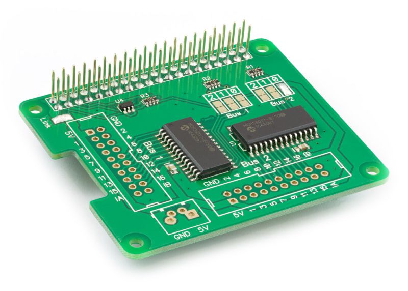
IOPi Plus board. The RPi 2x20 header is across the top. On the right are the I2C address pads for the two buses. On the left and bottom are the two 2x10 connector locations. I installed right-angle headers.

|
Function |
Bus 1 |
Bus 2 |
|
|
Wabbit/Turnout1 |
Wabbit/Turnout1 |
|
5vdc |
not used |
not used |
|
Ground |
to each Wabbit |
to each wabbit |
|
1 |
5/4 CLEAR |
2/2 CLEAR |
|
2 |
5/4 THROWN |
2/2 THROWN |
|
3 |
5/12 CLEAR |
2/8 CLEAR |
|
4 |
5/12 THROWN |
2/8 THROWN |
|
5 |
1/1 CLEAR |
4/3 CLEAR |
|
6 |
1/1 THROWN |
4/3 THROWN |
|
7 |
1/5 CLEAR |
4/9 CLEAR |
|
8 |
1/5 THROWN |
4/9 THROWN |
|
9 |
6/10 CLEAR |
Orange LED3 |
|
10 |
6/11 THROWN |
Blue LED3 |
|
11 |
6/11 CLEAR |
Orange LED3 |
|
12 |
6/10 THROWN |
Blue LED3 |
|
13 |
3/6 CLEAR |
not used |
|
14 |
3/6 THROWN |
not used |
|
15 |
3/7 CLEAR |
not used |
|
16 |
3/7 THROWN |
not used |
|
IA |
GPIO 42 |
GPIO 12 |
|
IB |
GPIO 02 |
GPIO 262 (not used) |
1 - See Wabbit Feedback Wiring
2 - See Unicorn HAT Wiring
3 - See Traffic Monitoring Wiring
