Test Tool
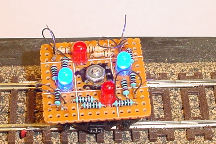
NOTE: This 'tool' was thought to be a good idea, it is NOT. This page is included for completeness. This page is included so as not to break links, but is not included in the index.
What I envisioned was an easy way to test for dead track/rail sections and to test for reverse polarity across joints in the track/rail. For a start I bought a power pickup truck that had four-wheel pickup. Although the "front" and "rear" wheels on each side were tied together, it was a start.
Given too much time to think about it the objectives of the tool became:
- Detect dead sections of track
- Detect dead sections of rail or a frog
- Detect reverse polarity across a rail joint or a frog
- Check for continuous power through a turnout or block of turnouts
The design needed to:
- Check power left-to-right between the rails
- Check power front-to-back along each rail
- Drop the from the 15v DCC to ~5v for the LEDs
- Limit the current threw the LEDs to <30ma
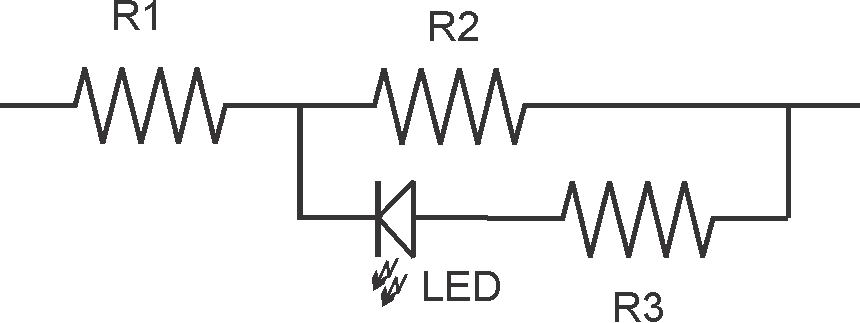
To manage #3 and #4 the following voltage divider was the starting point.
To get from 15v to 5v across the LED R1 must be twice the resistance of the right side of the diagram. Assuming the LED has no resistance in the forward direction, all three resisters can be the same size (R2 & R3 in parallel has 1/2 the resistance of R1 so drop 1/3 of the voltage ~ 5 v). In the reverse direction the LED is almost an open so R2 will drop 7.5v and be seen across the LED, which is good enough not to kill the LED. (no current threw R3, no voltage drop)
With 5v across the LED, R3 needs to be greater than166Ω for the current to be less than 30ma. As it turns out I didn't have 12 resisters (3 resistors x 4 test) that size. I did have 12 1,000Ω resisters. So, the current will be 5ma. At that low current the green LEDs I have aren't very bright but the blue ones are bright enough. Two more "as built" vs design.
Starting with the original pickup truck (sorry) top and bottom and taking it apart
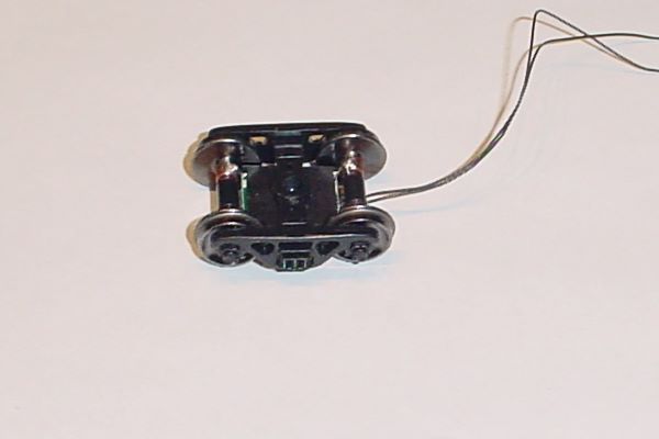
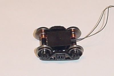

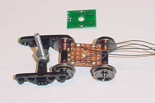
I unsoldered the original green circuit board, cut a new one the same size so it would fit in the protective plastic cover (you can't see), cut the wires between the front and rear axles ending up with four wires one from each wheel. I also filed down the head of a 4x40 screw so the head would fit in the recess making room for the board on the bottom and providing a mount for the board on top. After replacing the protective covers and rotating the wheels under the carriage, ready to build and attach the circuit board on top.

With four of the circuits above installed, two circuits with blue LEDs between the wheels on the front and rear axles, and two circuits with red LEDs between the front and rear wheels on each rail, the top circuit board was attached to the 4x40 screw with a nut. I did add two extra nuts underneath to give spacing above the top of the wheels.
On my test track, the photo at left show correct voltage between the wheels on the from and rear axles.
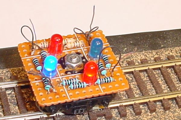
Moving the test truck to the joint between the main test track and the stub track at the right end, that is not powered, the right blue LED goes out showing no power on the "next" section of track.
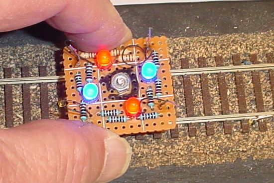
Changing the configuration of the test track so that the stub track is powered, but opposite the main section, the two red LEDs light.
The truck has very little weight so I had to hold it down to get good contact. Expect this is the way I will be using it anyway, holding it, pushing it around the track and across turnouts, checking the polarity of the frog, etc.
To answer your question, 'Why don't I just drive a loco around the track?' Because until I get the wiring a lot closer to done, the layout will be in the "Up" position and the train would fall off.
