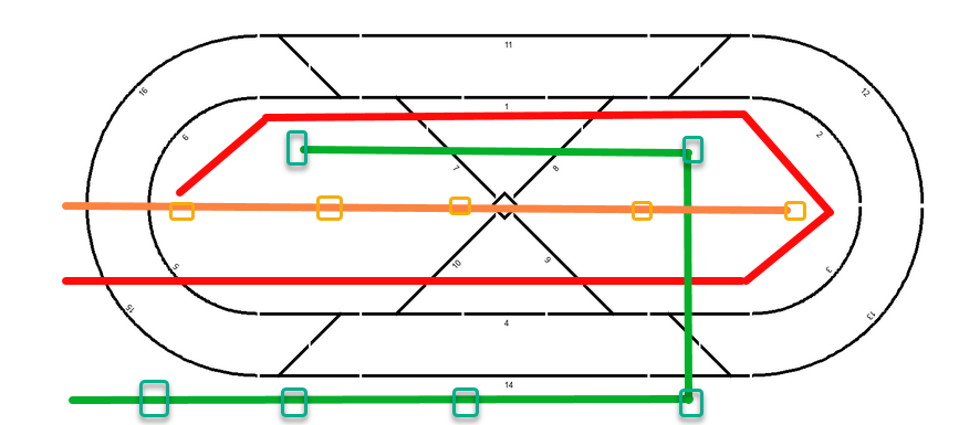
Power distribution
There are three levels of power distributed throughout the layout:
- 15vdc/DCC signal Red/White twisted pair
- 5v0dc Black/Green twisted pair
- 12vdc Orange/Blue twisted pair

The 15vdc and DCC bus were wired first, 15vdc to the DCC++ Base Station (Arduino/Motor Shield) and DCC signal from there throughout the layout shown by the red line above. Smaller wires were soldered to the bus through (not so) quick disconnects and then soldered to sections of the track. That approach worked but not well. I added connector blocks when installing the other buses.
The 5v0dc bus is more tightly regulated to provide power for the three two processors that are on the layout:
- Arduino/Motor Shield, Base Station (2).
- Raspberry Pi 4 controlling the semaphores and the Unicorn HAT signal display (3).
- Raspberry Pi 3 monitoring the state of the turnouts/switches (3A).
Less critically the 5v0dc also provides power for the:
- 12 bi-color LEDs sticking through the baseboard that show the state of the turnouts.
- 36 IR sensors under the track.
- 60 56 servos that move the semaphore arms.
- 24 optic-isolators providing the status of 12 switch/turnouts.
The 12vdc bus runs down the middle of the layout and provides power for the 60 LED lights on the semaphore poles and the 4 dwarf signals in the parking lot.
The three switching power supplies are mounted on a lag of the layout and plugged into a power strip on the other side of the lag. I got tired of reaching down to the power strip to turn things on so added a switched receptacle on the front leg just below the layout. (Getting old and lazy.)
