Design
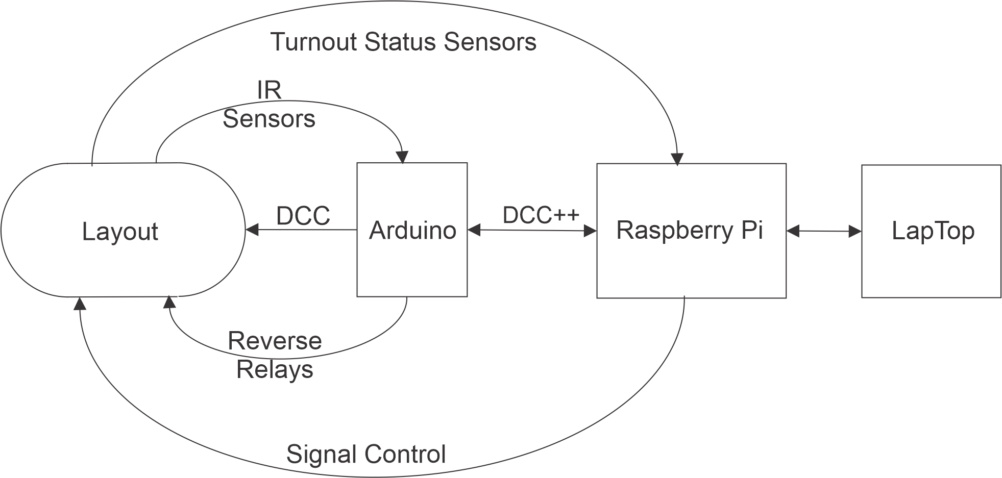
The overall end time design is as shown below:

- The double oval track layout described earlier consists of:
- The track physically/logically divided into 16 blocks. Two blocks, 7 & 8, are also electrically isolated so that the power can be reversed.
- 32 IR sensors, one sensor at each end of the 16 blocks of track. 4 additional IR sensors monitoring the four "parking" locations in the staging yard.
- 12 switches/turnouts. Four sets of 3 switches are electrically isolated from the track.
- 24 sensors to report status/position of the 12 turnouts.
- 28 dual head semaphore signals & 4 single head semaphore signals, one signal tower located at each end of the 16 track blocks "controlling" access to the next block. 4 tri-color LED signals "controlling" movement in the staging yard. (Two dual head semaphores not installed due to space constraints.)
- An Arduino Mega 2560 microcontroller with an Arduino Motor Shield running DCC++ Base Station software that:
- Receives serial DCC++ commands and modifying the DCC signal sent to the track, trains and other DCC elements.
- Monitors the 36 IR sensors embedded in the track reporting changes in status.
- Controls two relays to reverse the polarity of the DCC signal going to sections 7 or 8 of the track.
- Raspberry Pi 4 computer with four Adafruit 16-Channel PWM / Servo HAT/Bonnets, IOPi HAT, custom fan and interface for 2 Unicorn HATs. The Raspberry Pi will run custom software to:
- Pass DCC++ commands from the Laptop(4) through Raspberry Pi (3A) not intended for this computer to the Arduino(2).
- Pass DCC++ status messages from the Arduino(2) to the Raspberry Pi (3A) and onto the Laptop(4).
- Receive added DCC++ commands from the Laptop(4), through the Raspberry Pi (3A) to manage all signal control.
- Store configuration of signals :: servos :: Unicorn x, y.
- Return to the Laptop(4), through the Raspberry Pi (3A) status messages.
- Drive up to 60 (56) servos to control the aspect (position) of the semaphores signal arms.
- Control the aspect (color) of the 4 tri-color LED signals in the staging yard.
- Monitor Raspberry Pi CPU temperature and frequency.
- Control Raspberry Pi cooling fan based on temperature and frequency criteria.
- Control two Unicorn HAT HD displays reflecting the aspect of each semaphore and LED signal.
- Display on a Unicorn HAT HD relative temperature, frequency, fan status (on/off) and mode (auto/manual).
- Receive added DCC++ commands from the Laptop(4) to manage turnout status sensors.
- Store configuration of sensors :: GPIO pins.
- Return status or changes in status of each configured sensor.
- Display relative traffic density to/from the Arduino(2) and to/from Laptop(4)).
3A. Raspberry Pi #2 computer to provide 24 additional GPIO pins to input the state of the 12 turnouts in the layout. The Raspberry Pi will run custom software to:
- Pass DCC++ commands from the Laptop(4), not intended for this computer, to the Raspberry Pi 4 (3).
- Pass DCC++ status messages from the Raspberry Pi 4 (3) onto the Laptop(4).
- Receive added DCC++ commands from the Laptop(4) to manage turnout status sensors.
- Store configuration of sensors :: GPIO pins.
- Return status or changes in status of each configured sensor.
- Display relative traffic density to/from the laptop(4).
- Laptop running DecoderPro DCC++, JMRI or custom control software:
- GUI to manage the configuration of the Arduino(2), Raspberry Pi (3) and Raspberry Pi (3A)
- GUI to configure a run of the TrainThing hardware
- Based on (1) the assigned task and (2) the state of the TrainThing, reported by the Arduino (2) and Raspberry Pi (3A), the Laptop(4) will send DCC++ commands (through the Raspberry Pi (3A), to the Raspberry Pi (3) and Arduino (2) to:
- Control the DCC signal to the track, trains and other DCC elements.
- Control the state of the two reversing relays.
- Control the aspect of the semaphore and LED signals.
- Display a schematic of the current state of the TrainThing.
The following development phases are expanded and explained in following sections. Links to and from the Design phases and "The Process" will be included as the process precedes.
Phase I -- Use the laptop (4) to send DCC++ commands to the Arduino Mega 2560 (2)
and control the layout and trains (1).
- Build the layout (1).
- Add some structure to the simulator software (4)
- Start design, coding control software (4).
Phase II -- Develop preliminary software for Raspberry Pi (3) and (3A) to:
- Pass DCC++ commands from the laptop (4) to the Arduino (2) and return status from the Arduino to the laptop.
- Accept commands from the laptop to control the servos/semaphores.
- Add the turnout sensors to the layout.
- Return status from the turnout sensors to the laptop (4).
- Fix the Simulator.
Phase III -- Develop laptop (4) software to:
- Control the hardware (1) through commands sent to:
- the Raspberry Pi (3) (3A)
- Arduino (2)
- Control the hardware(1) based on:
- Assigned problem and
- Hardware status reported by Arduino (2) & Raspberry Pi (3).
